We’re excited to unveil one of our flagship products: an efficient and secure Data Acquisition System (DAS). Our team has designed this solution to meet the highest standards of data management and reliability.
Data acquisition systems are vital in various industries, from monitoring essential parameters in steel mills to ensuring optimal performance in research labs. Our DAS excels at collecting and processing data seamlessly, enhancing efficiency and safety across multiple applications.
Join us as we dive into the intricacies of this cutting-edge technology, designed to revolutionize how you manage and analyze data. Whether you’re aiming to improve operational efficiency, enhance data security, or simplify complex data integration processes, our DAS is the perfect solution.
First of all: what is DAS?
Data acquisition (DAS, DAQ, or DAU) is the process of sampling signals that detect physical phenomena and converting these samples into digital values that a computer can process. In simpler terms, it turns analog waveforms into digital data. Here are the main components of data acquisition systems:
- Sensors: Convert physical properties into electrical signals.
- Signal Conditioning Circuitry: Prepares these signals for digital conversion.
- Analog-to-Digital Converters (ADC): Convert the conditioned signals into digital values.
- Computing Unit: Once the ADC converts the analog signals into digital data, the computing unit, often a microprocessor, takes over. This unit processes the data, performs necessary calculations, and makes decisions based on predefined algorithms. It then presents the data to the user, enabling real-time monitoring, control, and analysis. The microprocessor is crucial for transforming raw data into actionable insights and ensuring seamless operation of the entire DAS.
These systems are often controlled by software written in various programming languages such as Assembly, BASIC, C, C++, C#, Fortran, Java, LabVIEW, Lisp, and Pascal. Data acquisition systems are commonly known as data loggers.
What is an Integrated Electronics Piezo-Electric (IEPE)?
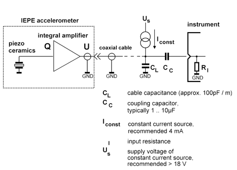
IEPE, or Integrated Electronics Piezo-Electric, refers to a technical specification for piezoelectric sensors with integrated electronics for impedance conversion. These sensors measure acceleration, force, and pressure, and are also used in measurement microphones. They are known by other names such as ICP, CCLD, IsoTron, or DeltaTron.
Here’s how IEPE sensors work:
- Integrated Electronics: The electronics convert the high-impedance signal from the piezoelectric material into a low-impedance voltage signal, usually around 100 ohms. Low-impedance signals can travel over long distances without losing quality, eliminating the need for special low-noise cables.
- Constant Current: The sensor operates with a constant current, usually between 2 and 20 mA, with 4 mA being the standard. Higher constant currents allow for longer cable lengths while maintaining signal quality. The current creates a positive bias voltage at the output, typically between 8 and 12 volts, which is added to the measurement signal.
- Power and Signal Transmission: Both the power supply and the sensor signal are transmitted through a single shielded cable, simplifying the setup.
- Compliance Voltage: The power source’s voltage, or compliance voltage, should be around 24 to 30 V to allow for the maximum signal range in both positive and negative directions.
A typical IEPE sensor uses about 100 mW of power at 4 mA constant current and 25 V compliance voltage, which can be challenging for battery-operated devices. However, low-power IEPE sensors are available, operating at just 0.1 mA of current from a 12 V supply, reducing power consumption by up to 90%.
Applications and Benefits of Data Acquisition Systems
Data acquisition systems (DAS) are versatile tools used across various industries to collect and analyze data. Here are some key applications:
- Electronics: Testing variables in electronics design, such as heat production, resistance, conductivity, and magnetics.
- Automotive Industry: Quality testing of produced parts in automotive manufacturing.
- Imaging: Quality testing of imaging equipment like photographic lenses and video cameras, as well as scientific equipment such as scanners and microscopes.
- Laser Technology: Testing laser performance, light intensity, and color.
- Sonar-Radar: Evaluating the efficiency and effectiveness of radar and sonar systems using remote sensing technologies.
- Industrial Machines: Testing the tolerance of industrial machines to repetitive forces, ensuring their reliability and repeatability.
- Non-Destructive Testing: Used in the non-destructive testing of structures, geology, seismology, ultrasonic measurements, and acoustic emission analysis.
- Gas Detection: Using gas detectors with tracer gases like hydrogen and helium. The gas loss is measured with a mass spectrometer to determine the amount and composition of the escaping gas, helping to identify leaks in systems or machines.
The Downsides of Data Acquisition Systems You Should Know About
Here’s what you need to consider when setting up a Data Acquisition System:
- High Setup Costs: Establishing a data acquisition system can be expensive due to the need for specialized hardware and software, resulting in substantial overall costs.
- Complex Setup and Maintenance: These systems require expertise in both hardware and software components, making their configuration and maintenance processes complex and challenging.
- Compatibility Issues: Ensuring smooth integration of various sensors and equipment can be problematic, leading to potential compatibility challenges.
- Data Security Concerns: Storing sensitive information in these systems without proper cybersecurity measures increases the risk of data breaches.
- Ongoing Maintenance: Regular maintenance is essential for optimal system operation, but it adds to the overall cost and effort involved in implementation.
At Digital Gate, we strive to address these challenges with our DAS solutions, providing you with the tools you need to succeed in your industry.
What is Condition Monitoring?
Imagine having a maintenance strategy that gives you a real-time heads-up about the health and safety of your machinery. That’s what condition monitoring (CM) offers. Using advanced machine monitoring software and sensors that detect vibrations and other factors, CM provides a comprehensive, plant-wide view of your mechanical processes. Plant maintenance technicians can remotely check the health of any machine, and the system sends alerts when there’s a change in machine health. This means your maintenance team can check it right away, addressing issues before they escalate.
What is Predictive Maintenance?
Predictive maintenance (PdM) takes it a step further. By leveraging data analysis tools and methodologies, PdM helps identify irregularities in your operations and potential equipment flaws before they lead to failure. This strategy minimizes the need for unexpected repairs and reduces the costs associated with excessive preventative maintenance. Essentially, PdM ensures that maintenance is done only when necessary, optimizing both time and resources.
Benefits of Condition Monitoring and Predictive Maintenance
Adopting condition monitoring represents a significant leap forward for many manufacturers. It not only enhances the safety of plant workers but also minimizes scheduled maintenance downtime and prevents unexpected equipment failures. By addressing known issues and repairing multiple machines simultaneously, plant managers can achieve greater efficiency and cost savings.
Even though condition monitoring has long been a reliable maintenance tool, more manufacturing businesses are starting to see its value. Modern condition monitoring systems offer substantial financial, operational, and safety benefits. Manufacturers implementing condition-based maintenance procedures enjoy higher reliability and efficiency, with a low risk and high reward scenario.
Predictive maintenance further optimizes machine maintenance by performing it only when necessary, right before a failure is likely to occur. This approach results in several cost savings:
- Reducing maintenance time
- Minimizing downtime due to maintenance
- Lowering costs for supplies and replacement parts
Studies show that predictive maintenance systems can boost ROI by threefold, reduce maintenance expenses by 25-30%, decrease failures by 70-75%, and cut downtime by 35-45%. However, these savings come with initial costs, as some condition monitoring methods can be pricey and require specialized expertise for successful data processing.
Project Requirements: What You Need to Know
For this project, here are the essential requirements to keep in mind:
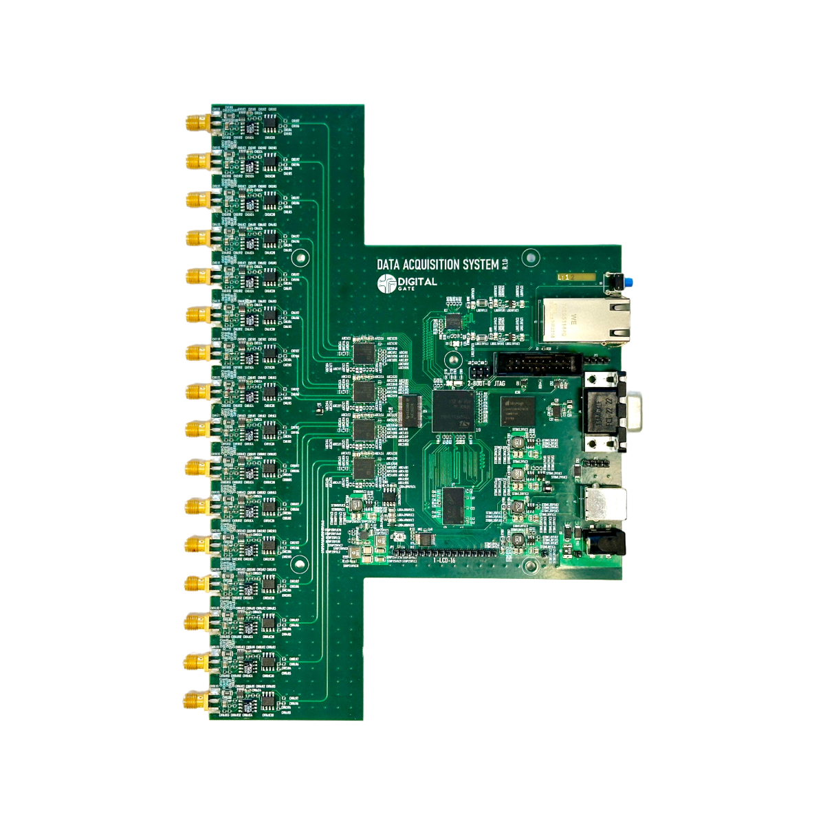
- Up to 16 Channel Analog Inputs: The system must support 16 separate analog input channels, allowing for extensive data collection from multiple sensors.
- Ethernet Connectivity with PoE and Auxiliary Power: Reliable Ethernet connectivity is crucial, featuring Power over Ethernet (PoE) to simplify wiring and an auxiliary power option for added flexibility.
- USB Connectivity: USB ports are necessary for straightforward configuration and data transfer, ensuring easy access and management of the system.
- External Power Connector: To accommodate various power sources, an external power connector is essential.
These features collectively ensure that the system is highly functional, versatile, and capable of handling complex data acquisition tasks efficiently.
System Specifications: A Closer Look
To give you a comprehensive understanding of our Data Acquisition System (DAS), here are the detailed specifications:
Processor
- STM32 Dual-Core Processor, 650 MHz: This powerful dual-core processor ensures efficient handling of multiple tasks simultaneously, providing the necessary computational power for complex data processing and real-time monitoring.
Memory
- 4 GB DDR3L RAM at 933 MHz: With 4 GB of DDR3L RAM, the system can smoothly run applications and manage data without lag. The 933 MHz speed ensures quick access to stored information, enhancing overall system performance.
Storage
- 4 GB eMMC: The embedded MultiMediaCard (eMMC) provides 4 GB of reliable and fast storage, perfect for holding the system’s firmware, software, and essential data. Its robust design ensures durability and longevity.
Analog Channels
- 16 Analog Input Channels: The system supports 16 separate analog input channels, allowing you to connect multiple sensors and gather a wide range of data for comprehensive analysis.
System Connectivity: Ensuring Seamless Integration
Ethernet Connectivity
- Ethernet with PoE and Auxiliary Power: Ethernet connectivity provides high-speed data streaming capabilities. The Power over Ethernet (PoE) feature simplifies installation by allowing power and data transmission over a single cable, while the auxiliary power option ensures the system remains operational in various scenarios.
USB Connectivity
- USB-C for Configuration: USB-C ports offer easy and quick configuration options. Whether you need to update firmware, adjust settings, or transfer data, the USB connectivity ensures a user-friendly experience.
These detailed specifications highlight the robust and versatile nature of our Data Acquisition System, making it a reliable choice for a wide range of applications.
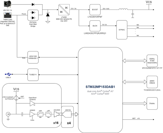
Power design
For this project, we decided on Power over Ethernet (PoE) and an auxiliary power input. After voltage regulation by the LT4925, the power is split into two 12V rails for the BUCK and BOOST converters. The BOOST converter supplies the necessary 25V for the frontend current sources, while the BUCK converter steps down from 12V to 5V for the PMIC of the MPU, which then manages all the required rails (1.8V for VDD, 3.3V for peripherals, etc.).
Frontend design
The front end includes 16 analog channels that can connect to 16 IEPE sensors. Each channel has a current source for the sensors and two OP AMPs creating the differential signal needed for the ADC. We use one ADC for every four channels, requiring a total of only four ADCs. Sampling is done simultaneously on all 16 channels.

Conclusion
At Digital Gate, our custom Data Acquisition System (DAS) is built to excel in predictive maintenance and condition monitoring. It improves operational efficiency, enhances data security, and simplifies data integration. Whether you’re in steel manufacturing, research labs, or any industry needing precise data, our DAS is designed to meet your needs and go beyond your expectations.
Do you have any ideas or feedback on this project? Interested in collaborating or need similar solutions? Contact us today and let’s innovate together!