Using our carefully designed board, we demonstrate the impressive power and flexibility of integrating modern technologies into motor controllers. In the realm of small to mid-range BLDCs, characterized by prevalent 24V and 48V ratings, we have embarked on a venture by introducing Gallium Nitride (GaN) power output stages. GaN offers the distinct advantage of elevated breakdown voltage, enabling us to cater to both 24V and 48V drive requirements without compromise. The power train architecture is meticulously crafted to withstand voltages of up to 100 volts, ensuring robust performance across varying operational parameters.
We incorporated in our design the controller from Performance Motion Devices. Due to its low resistance, we eliminated the need for a large heatsinks and we maintained optimal temperature for the 10 A motors. Each MOSFET in the system consumes less than 50mW of power when the motor is running at 10 A continuously, demonstrating the system’s effective heat management capabilities. Additionally, our design can easily adapt to increased power needs through incorporating supplementary transistors.
To lead into with our system, we found that using CAN communication is the best method for our application. Compared to other options like RS232 or SPI, CAN is more versatile. It makes it easy to add more channels to the system without needing lots of extra development work. The flexibility offered is particularly advantageous, whether you are still in the process of developing your project or laying out alternatives for the integrators who will utilize it.
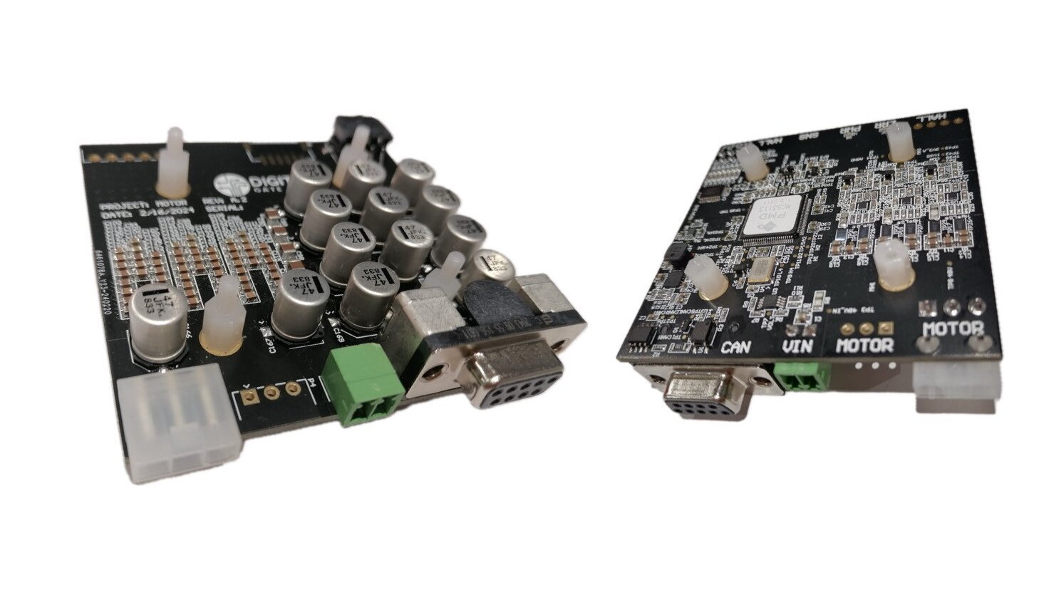
Figure 1 – Fully assembled boards
Applicable sectors for our Custom Motor Controller:
• Industrial Automation: Motion control is used to coordinate and control multiple motors for specific movements. For example, in manufacturing, packaging, and assembly, motion control helps plan precise movements and coordinates speeds smoothly. There are many important parts of a motion control system, two of them being the motion controller that plans movements and the control motor drivers. The motor drivers convert control commands into powerful signals for the motors which are moving according to the control commands and to the precise position that sensors are giving.
• Robotics and Manufacturing: Motion control ensures smooth movement of robotic arms, conveyor belts, and other automated systems. Processes like CNC milling, 3D printing, and welding rely on motion control for accurate positioning and operation.
• Entertainment and Gaming: Motion control makes gaming more realistic by enabling lifelike movements in virtual worlds. It is also used in amusement park rides, simulators, and interactive displays to make experiences more engaging.
• Healthcare and Medical Devices: Motion control is used in medical imaging, lab automation, and surgical robots to perform safe and accurate procedures, improving patient outcomes and efficiency.
• Textile and Printing Industries: Motion control systems are vital for handling fabrics precisely in textile machinery and placing ink accurately in printing presses, maintaining consistent quality and efficiency.
• Security and Defense: Motion control is crucial for operating surveillance cameras, drones, and security systems, allowing precise tracking and positioning. It is also important in radar systems, missile guidance, and unmanned vehicles for mission success and effectiveness.
Controller Architecture
Our architectural design stands out due to its unique controller, which is responsible for regulating motor movements, receiving signals regarding speed and direction, and regulating motor operations. Furthermore, our system integrates crucial sensors that provide essential performance data. Ensuring optimal functionality, the power supply delivers the accurate amount of power required by the motor. Moreover, our dynamic power train is engineered to endure voltages of up to 100 volts, housing 10A motors and boasting exceptional efficiency attributed to minimal channel resistance. To facilitate user interaction, the interface enables intuitive engagement with the motor controller, incorporating features such as LEDs and buttons for enhanced usability.
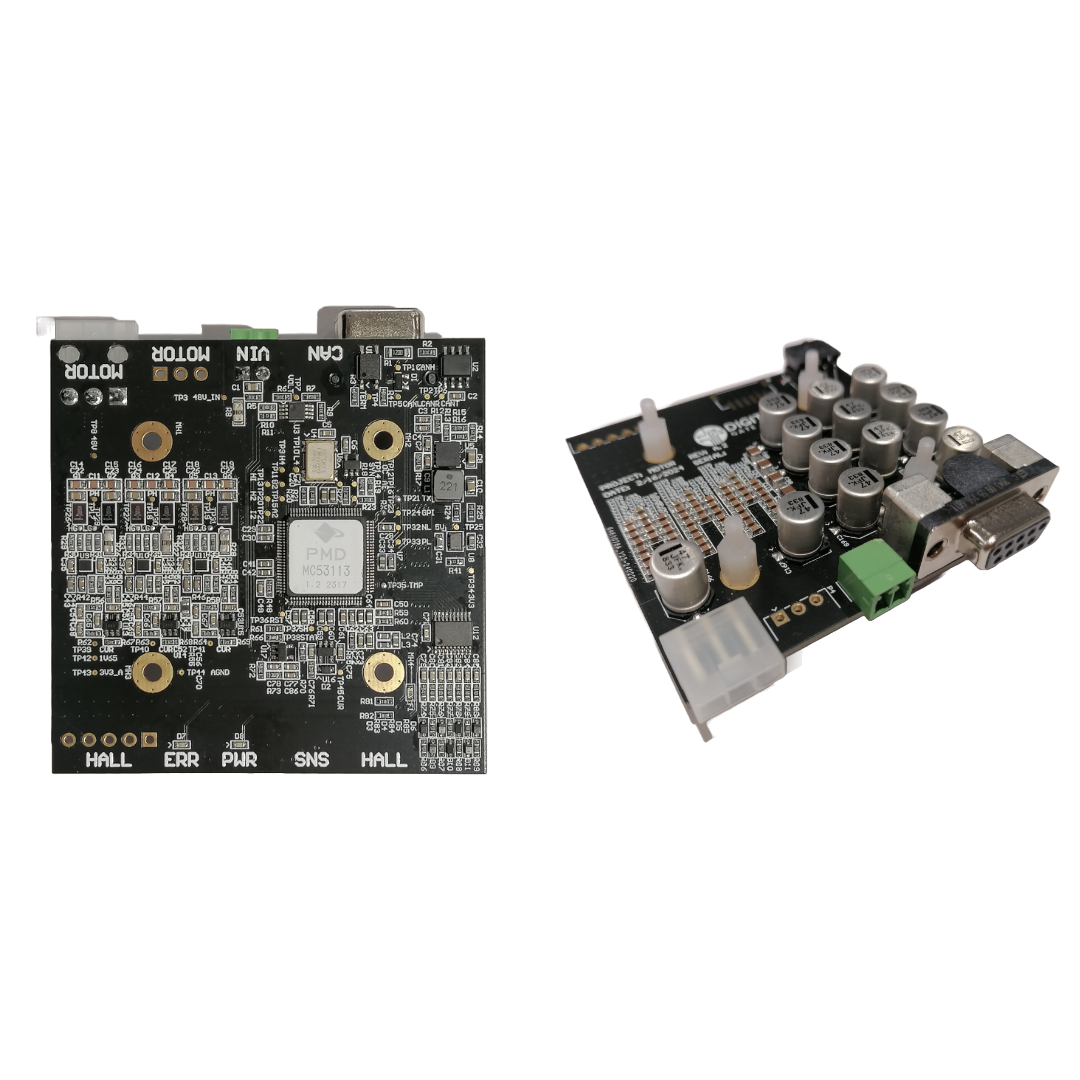
Figure 2 – Fully assembled boards
Optimizing Motor Controller System
For the selected motors, we need to use specific connectors to make sure they get enough power. We are using 6-pin Micro-Fit connectors (part number 430450609) and Mini-Fit Jr. connectors which stand out by being strong and reliable. To make sure we can connect the motors and have backups, we will also use Screw terminals Wuerth WR-TBL series 3221. They can operate at high current, of 10 A, depending on the version. We will use different connectors with 2 to 5 poles for more options. Also, the interface controller is equipped with SMT DB9 connector which saves money and space.
How we use the controller
The hall and encoder inputs are carefully designed to work with digital signals at 3.3 volts, but they can handle up to 5 volts without any problems. For the best performance, any analog input signals that are not being used, like ANALOG1 and CURRENTD, should be connected to AnalogGND. If some inputs are not connected at all, it is okay to leave them as they are. We have included test points on all unused pins to simplify the troubleshooting process.
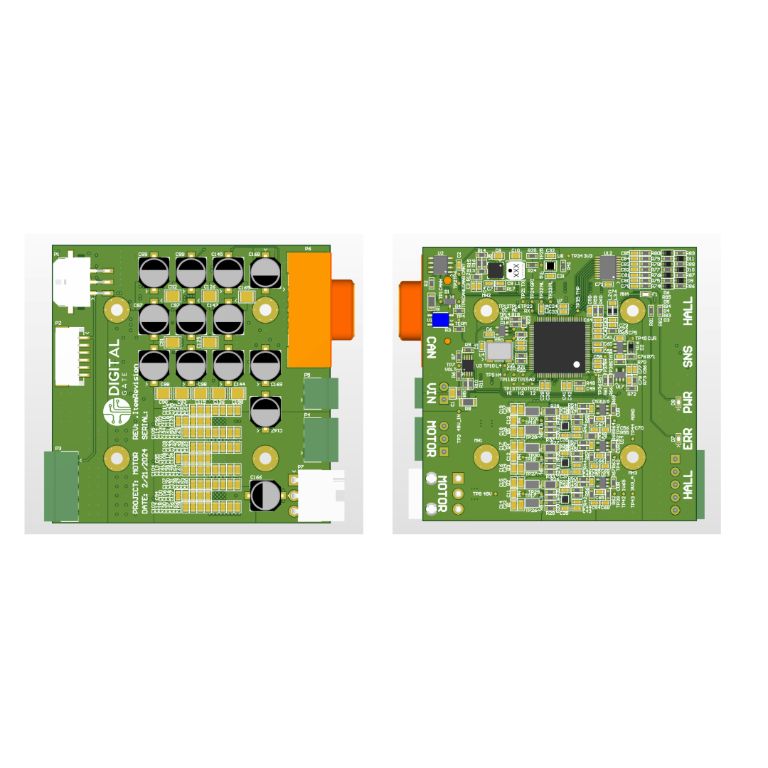
Figure 3 – Motor controller board, bottom view
The Power Supply
It is important for our system to accurately measure the voltage and current of the power supply. Onour design, we use a setup where the voltage is measured using a combination of resistors that add up to 21.1k ohms. Each 10k resistor in this setup can handle up to 81mW of power when the voltage reaches 60V. We make sure the maximum voltage does not go over 63.3V to keep everything in the safety margin. For measuring current, we follow the standards used for PMD evaluation, which gives us an output of 66.5mV for every amp of current. This lets us measure up to +25A of current. We also include an 11k ohm resistor to match the sensitivity of the leg sensor.
We used EPC evaluation boards, which has an 8V turn-on UVLO. This setup can be adjusted to use different configurations like 43/75k or 150k/27k to accommodate unique needs. The total load for the power supply, including both digital and analog components, is maximum peak consumption 1.5 W. We are paying close attention to making sure the power is distributed efficiently.
For the +3.3V power supply, we use the MYRGP330060W21RC DC/DC module from Murata, which has an average efficiency of around 86%. We separate the digital and analog parts of the +3.3V power supply using ferrite beads, with the analog part using about 27mA of power. We also adjust the number and values of ceramic capacitors to make sure everything runs smoothly on the board.
The driver we use
When we chose the driver for our project, we carefully looked at all the details and factors that have a vital impact on the success of the project’s outcome. One of the options, the DRV8316, is convenient because it has built-in current sensors, but it can only handle up to 40V and 8A. Another option, the MP6541A, is similar, but it also has the same limits on voltage and current. The DRV8323RH is cheaper and has a built-in buck converter and amplifier, but it needs external MOSFETs to work. The AMT49100 is similar but also needs external MOSFETs and relies on SPI control. The FDMF8811 and LMG5200 do not have effective ways to dissipate heat, which is a problem.
Even though options like the DRV8316 are tempting because they are all-in-one solutions, in the end we decided to go with a Gallium Nitride power output stage because it has some advantages, like being able to handle higher voltages. This choice lets us work with both 24V and 48V drives, which fits our project goals. We based our power stage design on examples like the EPC2065 and GAN3R2-100CBE, which have similar features and superior performance. While these transistors work in sets, we found that individual transistors are enough for what we need.
For measuring current, we followed a method outlined in the MC58113 specifications and adjusted the conversion ratio accordingly. We use a 10k 0805 NTC placed in the hottest/critical region of the board. We also followed guidelines for decoupling capacitors, using the right sizes for the best performance. These careful decisions have ensured that our solution is strong and tailored to meet our project goals within our timeline.
Our solution for the interface
To create a strong interface setup, we have chosen the SN65HVD233DR driver, which meets the standards of the development board we are using. Since we need to handle 5V CAN bus systems, which can use a lot of power, we have selected the right components carefully. For our 3.3V bus, we have chosen a 0.25W 1206 resistor to ensure its functionality.
Since we already have a 4-point system in place, we need the MC51113, that has a spare GPIO to drive it. To do this, we used a FET output photo relay, controlled by the AXISOUT general purpose output of the MC58113. This solution needs to handle a current load of 41mA. We used the TLP175A, which can handle up to 100mA, to make sure everything works smoothly.
For the LED, which has a typical forward current of 5mA, and a forward voltage drop of 1.2V, we needed to choose the right resistor to limit the current flow. Based on calculations, we need a resistor with a resistance of around 42Ohm to keep the power dissipation within safe limits, which is about 0.11W. So, using two 22Ohm 0.1W resistors in series will do the job well, ensuring the interface setup works reliably.
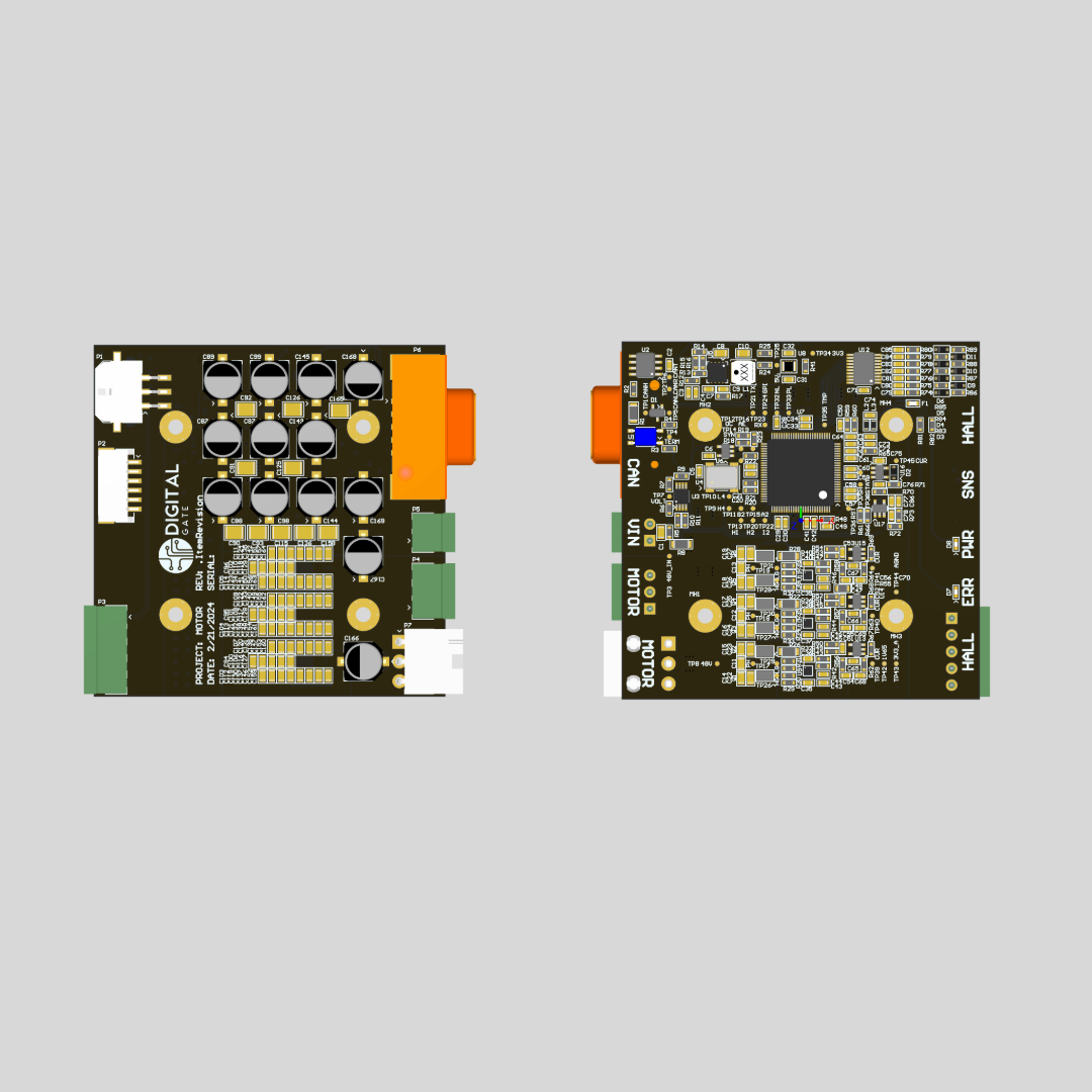
Figure 4 – Motor controller board, top view
Our solution for the interface
We found modules that offer 200mm of travel length and are designed for NEMA23 Linear Actuator Precision workstations. These modules include features like ball screws, linear guideways, and servo motor capabilities, making them a good fit for CNC Router X, Y, Z axis. They provide support accessories like the support metallic stepper Nema23, which helps us integrate the moving motor onto the carriage, improving how well everything works together.
Conclusion
In conclusion, our custom motor controller marks a big step forward in motion control technology. By carefully designing and combining advanced parts like motion controllers, motor drivers, and position sensors, our system delivers precise, reliable, and efficient performance for industrial and automation needs. We go beyond by using innovative technologies like Gallium Nitride power stages and CAN communication, giving even better performance and flexibility. Our controller can grow with industry needs, because of its scalability, while its strong build and smart control to ensure its long-term functionality. As we move forward with this innovation, our motor controller is set to change the way motion control works, bringing progress and success to many different fields worldwide.