Is the capacitance of the capacitor always same?
Multilayer ceramic capacitors (MLCCs) offer several advantages that make them a popular choice for various electronic applications, including high energy density, low cost, and a wide range of capacitance options. However, they are not without drawbacks, one of which is the capacitance reduction effect when subjected to a constant or DC voltage. This effect is commonly referred to as “DC bias” and information dedicated to this phenomenon can be found on manufacturers’ websites.
Among engineers, the rule of thumb is to use a capacitor with a nominal voltage rating 1.5-2 times higher than the operating voltage. However, in certain cases where maximum Bill of Materials (BOM) optimization is required, one might wonder if it is possible to use a 16V X5R MLCC in a circuit with a 10V working voltage. What would happen to the capacitance in such a scenario? How undesirable would its reduction be?
Moreover, what if the voltage increases only for a few seconds? In this article, we will delve into the theoretical underpinnings of this issue and explore its practical solutions.
The Source of the Problem
The issue lies with the material BaTiO3, which serves as the dielectric in capacitors. When subjected to an alternating voltage, dipoles in BaTiO3 can freely reorient under the influence of an electric field, providing capacitance for charge storage. However, when a DC voltage is present, a portion of the dipoles becomes “locked” and cannot fully reorient. This reduces the effective capacitance of the capacitor for noise suppression or ripple smoothing.
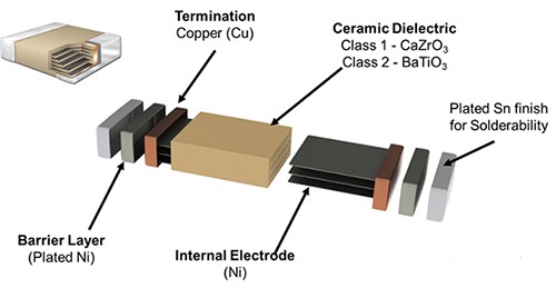
Figure 1 – The structure of the MLCC capacitor (Image source: KEMET)
DC Voltage and Manufacturer Influence
As mentioned earlier, increasing the DC voltage on the capacitor intensifies the locking of dipoles by the electric field. As a result, its capacitance decreases closer to the nominal voltage. The magnitude of this reduction depends on the manufacturer’s technology since each uses unique manufacturing methods. An example of such a reduction is shown below.
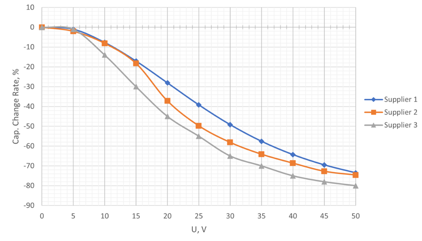
Figure 2 – Capacitance Loss with DC Bias on 1µF 50V X7R Capacitor in MLCC 0805 Package from Three Different suppliers.
Size
The capacitor’s size strongly influences its effective capacitance. Smaller dielectrics result in a higher percentage of dipoles being locked by the constant voltage, thereby intensifying the effect on capacitance. This means that the impact of voltage will vary for identical capacitors in different package sizes. An example is illustrated for 1µF ±10% X7R 25V capacitors in various packages.
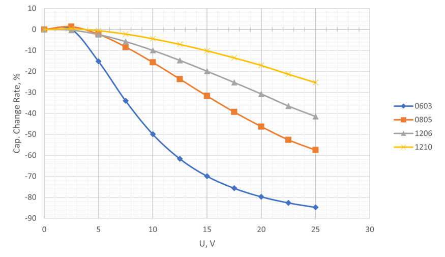
Figure 3 – Capacitance Loss with DC Bias on 1µF 50V X7R Capacitor in different packages.
Dielectric
Using a higher-quality dielectric is one way to preserve effective capacitance. Dielectrics of the first class (NP0, C0G) eliminate DC bias issues. However, such dielectrics are expensive and typically reserved for critical applications. More commonly used are second-class dielectrics like X8L, X7R, X5R, etc. Figure 4 demonstrates how the DC bias varies depending on the dielectric type, even though different dielectric types might have similar bias values in some cases.
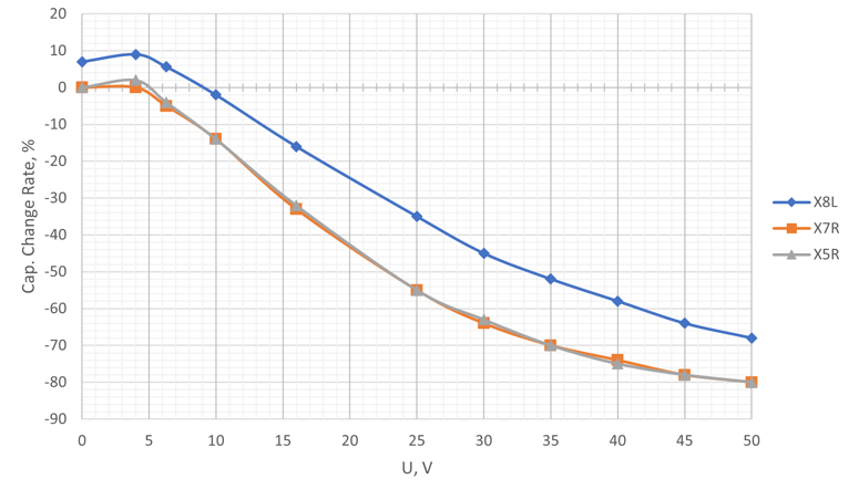
Figure 4 – Capacitance Loss with DC Bias on 1µF 50V 0805 Capacitor in different dielectrics.
Capacitance
At first glance, it might seem that using a capacitor with a higher capacitance value would result in higher effective capacitance. However, this is not always the case. Sometimes, a capacitor with a higher capacitance can experience a more significant reduction. This is because a higher capacitance within the same package size leads to a higher density of dipoles per unit volume. Consequently, when subjected to the same electric field (i.e., constant voltage applied), a larger number of dipoles get locked, resulting in lower effective capacitance. Figure 5 demonstrates such behavior for 1µF ±10% X7R capacitors in the 0603 package with varying nominal voltages.
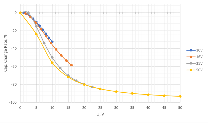
Figure 5 – Capacitance Loss with DC Bias on 1µF 50V X7R 0603 Capacitor in different dielectrics.
Time
The voltage drop does not occur instantaneously, and it takes some time for the dipoles to become “locked.” It is essential to understand this to avoid fearing a capacitance decrease due to short-duration voltage spikes. According to the graph in Figure 6, the most significant capacitance drop occurs within the first 1-3 minutes. However, it does not stop there; the reduction continues even after an hour, two hours, or even 100 hours.
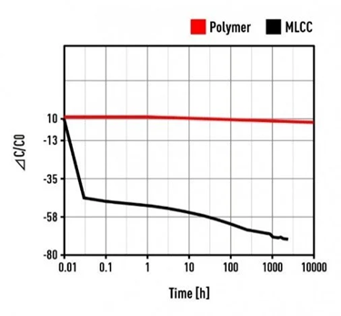
Figure 6 – Capacitance drop with time under DC Voltage BIAS (Image source: Panasonic)
Conclusions
Summing up, we can highlight the main methods to preserve effective capacitance:
• Using a larger package size
• Employing high-quality dielectrics
• Using capacitors with higher voltage ratings
• Using capacitors with a small margin in nominal capacitance
Nevertheless, each of these rules has exceptions, which is why, at DigitalGate, we always verify the DC Bias for each capacitor on the manufacturer’s website during the design phase to ensure our clients’ devices operate without any issues. By being mindful of the impact of DC Bias and employing appropriate mitigation strategies, engineers can optimize their electronic designs for improved performance and reliability.
About the Author:
Vladislav Mokluza is a Hardware Engineer who specializes in circuit design and PCB development in DigitalGate. DigitalGate has been offering innovative hardware and software development services for state-of-the-art embedded systems, in accordance with the quality standards of the respective industries. Due to the fact that we are a flexible and competitive company, we have clients all over the world, especially in north America, Europe and Asia.